") 如何使用雙極電機(jī)創(chuàng)建3點(diǎn)軸機(jī)械臂
如何使用雙極電機(jī)創(chuàng)建3點(diǎn)軸機(jī)械臂

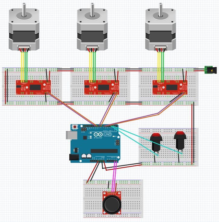
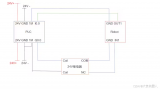
步驟1:原理圖和組件列表

這是我們?cè)诖隧?xiàng)目中使用的完整原理圖和可用組件的概述。
包含的組件如下:
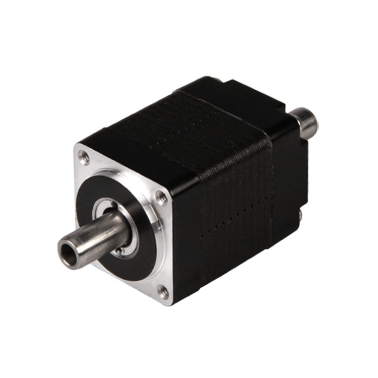
Berger Lahr雙極步進(jìn)電機(jī)(已安裝在機(jī)械臂上)
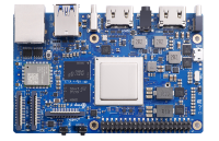
Arduino UNO
PlayStation2游戲桿
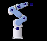
Cyber 310機(jī)械臂
超聲波接近傳感器HC-SR04
面包板
PlayStation2 RC直升機(jī)的振動(dòng)電機(jī)和轉(zhuǎn)子
EasyDriver 4.4步進(jìn)電機(jī)驅(qū)動(dòng)器
我們主要選擇這些組件是因?yàn)樗鼈兒苋菀诪槲覀兪褂谩N覀冞€認(rèn)為,與同班同學(xué)相比,使用更大的機(jī)械臂會(huì)很有趣。盡管我們意識(shí)到了這一點(diǎn),但我們的野心超出了我們的能力。
步驟2:構(gòu)造操作設(shè)備
我們焊接并連接了幾部分印刷品和許多電線,以便獲得適當(dāng)?shù)倪\(yùn)行電路來控制我們的機(jī)械臂。
設(shè)計(jì)本身主要基于盡管在實(shí)際施工過程中進(jìn)行了一些修改,但本節(jié)上面概述的概述中沒有提及。
步驟3:對(duì)其中的一些進(jìn)行了實(shí)現(xiàn),以實(shí)現(xiàn)超聲傳感器。
步驟3:機(jī)器人手臂的測(cè)試代碼
下面包含的機(jī)械手測(cè)試代碼
我們使用這段代碼來測(cè)試機(jī)械臂是否在實(shí)際工作,因?yàn)槲覀兒茈y對(duì)完整代碼(包含在步驟6中)做出反應(yīng)。該代碼的某些部分已過時(shí),因?yàn)閷?shí)際設(shè)備中未使用它。
#define step_pin 6 // Pin 6 connected to Steps pin on EasyDriver
#define dir_pin 7 // Pin 7 connected to Direction pin
//#define MS1 5 // Pin 5 connected to MS1 pin
//#define MS2 4 // Pin 4 connected to MS2 pin
#define SLEEP 10 // Pin 10 connected to SLEEP pin
#define X_pin A0 // Pin A0 connected to joystick x axis
int direction; // Variable to set Rotation (CW-CCW) of the motor
int steps = 1025; // Assumes the belt clip is in the Middle
void setup() {
// pinMode(MS1, OUTPUT);
// pinMode(MS2, OUTPUT);
pinMode(dir_pin, OUTPUT);
pinMode(step_pin, OUTPUT);
pinMode(SLEEP, OUTPUT);
digitalWrite(SLEEP, HIGH); // Wake up EasyDriver
delay(5); // Wait for EasyDriver wake up
/* Configure type of Steps on EasyDriver:
// MS1 MS2
//
// LOW LOW = Full Step //
// HIGH LOW = Half Step //
// LOW HIGH = A quarter of Step //
// HIGH HIGH = An eighth of Step //
*/
// digitalWrite(MS1, LOW); // Configures to Full Steps
// digitalWrite(MS2, LOW); // Configures to Full Steps
}
void loop() {
while (analogRead(X_pin) 》= 0 && analogRead(X_pin) 《= 100) {
if (steps 》 0) {
digitalWrite(dir_pin, HIGH); // (HIGH = anti-clockwise / LOW = clockwise)
digitalWrite(step_pin, HIGH);
delay(1);
digitalWrite(step_pin, LOW);
delay(1);
steps--;
}
}
while (analogRead(X_pin) 》 100 && analogRead(X_pin) 《= 400) {
if (steps 《 512) {
digitalWrite(dir_pin, HIGH); // (HIGH = anti-clockwise / LOW = clockwise)
digitalWrite(step_pin, HIGH);
delay(1);
digitalWrite(step_pin, LOW);
delay(1);
steps++;
}
if (steps 》 512) {
digitalWrite(dir_pin, HIGH);
digitalWrite(step_pin, HIGH);
delay(1);
digitalWrite(step_pin, LOW);
delay(1);
steps--;
}
}
while (analogRead(X_pin) 》 401 && analogRead(X_pin) 《= 600) {
if (steps 《 1025) {
digitalWrite(dir_pin, HIGH);
digitalWrite(step_pin, HIGH );
delay(1);
digitalWrite(step_pin, LOW);
delay(1);
steps++;
}
if (steps 》 1025) {
digitalWrite(dir_pin, HIGH);
digitalWrite(step_pin, HIGH);
delay(1);
digitalWrite(step_pin, LOW);
delay(1);
steps--;
}
}
while (analogRead(X_pin) 》 601 && analogRead(X_pin) 《= 900) {
if (steps 《 1535) {
digitalWrite(dir_pin, HIGH);
digitalWrite(step_pin, HIGH);
delay(1);
digitalWrite(step_pin, LOW);
delay(1);
steps++;
}
if (steps 》 1535) {
digitalWrite(dir_pin, HIGH);
digitalWrite(step_pin, HIGH);
delay(1);
digitalWrite(step_pin, LOW);
delay(1);
steps--;
}
}
while (analogRead(X_pin) 》 900 && analogRead(X_pin) 《= 1024) {
if (steps 《 2050) {
digitalWrite(dir_pin, HIGH);
digitalWrite(step_pin, HIGH);
delay(1);
digitalWrite(step_pin, LOW);
delay(1);
steps++;
}
}
}
步驟4:傳感器代碼
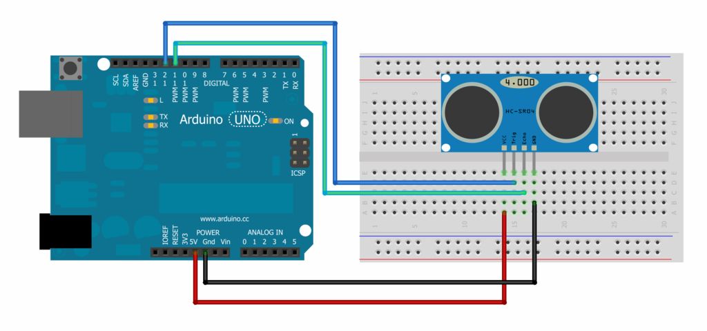
包括超聲波傳感器的代碼
為傳感器選擇的代碼經(jīng)過構(gòu)造,以便當(dāng)風(fēng)扇在以下范圍內(nèi)注冊(cè)對(duì)象時(shí)風(fēng)扇將運(yùn)行。距回波點(diǎn)10至20厘米。
盡管我們同時(shí)更改了引腳和范圍,但物理構(gòu)造仍基于上面的示意圖。
/*
HC-SR04 Ping distance sensor:
VCC to arduino 5v
GND to arduino GND
Echo to Arduino pin 8
Trig to Arduino pin 9
*/
#define echoPin 11 // Echo Pin
#define trigPin 12 // Trigger Pin
#define LEDPin 8 // Onboard LED
int maximumRange = 20; // Maximum range needed
int minimumRange = 10; // Minimum range needed
long duration, distance; // Duration used to calculate distance
void setup() {
Serial.begin (9600);
pinMode(trigPin, OUTPUT);
pinMode(echoPin, INPUT);
pinMode(LEDPin, OUTPUT); // Use LED indicator (if required)
}
void loop() {
/* The following trigPin/echoPin cycle is used to determine the
distance of the nearest object by bouncing soundwaves off of it. */
digitalWrite(trigPin, LOW);
delayMicroseconds(2);
digitalWrite(trigPin, HIGH);
delayMicroseconds(10);
digitalWrite(trigPin, LOW);
duration = pulseIn(echoPin, HIGH);
//Calculate the distance (in cm) based on the speed of sound.
distance = duration/58.2;
if (distance 》= maximumRange || distance 《= minimumRange){
/* Send a negative number to computer and Turn LED ON
to indicate “out of range” */
Serial.println(“fuckboy”);
digitalWrite(LEDPin, LOW);
}
else {
/* Send the distance to the computer using Serial protocol, and
turn LED OFF to indicate successful reading. */
Serial.println(distance);
digitalWrite(LEDPin, HIGH);
}
//Delay 50ms before next reading.
delay(50); }
步驟5:一點(diǎn)點(diǎn)視頻(和麻煩)
上面的精選視頻顯示了我們最大的問題之一。
我們根本沒有足夠的視頻電壓功率來運(yùn)行機(jī)械臂本身。機(jī)器肯定在接收信號(hào),但是它很小,甚至不能轉(zhuǎn)動(dòng)旋鈕來驅(qū)動(dòng)手臂的軸點(diǎn)。
主要問題集中在為機(jī)器人提供正確的電壓。電機(jī),由于最大輸入功率之間的差異,您可以放心地將其輸入到Arduino和使實(shí)際電機(jī)本身正常運(yùn)行所需的功率中。
步驟6:完整的主控制代碼
下面包含了機(jī)械手臂的完整代碼。
我們使用的代碼存在一些問題,但是由于我們?cè)陔妷汗β史矫嬉泊嬖谝恍﹩栴},如步驟5所述,我們很難對(duì)所有這些進(jìn)行分類。應(yīng)該注意的是,此部分代碼不包含傳感器的代碼。
#ifndef _stepLib_h_
#define _stepLib_h_
#include “Arduino.h”
// define our stepper class
class stepMotor {
public:
stepMotor(byte stepPin, byte dirPin); // our stepper object with variables stepPin and dirPin
void step(unsigned int stepFreq); // our stepping function which takes as an input our stepping frequency
private:
unsigned long _time; // current time
unsigned long _lastStepTime; // time at which we last stepped
unsigned long _stepPeriod; // time between a half period - this is the same as our delay(X) of part 1
byte _stepPin;
byte _dirPin;
boolean _stepCycle; // defines if we are on the HIGH or LOW side of our step cycle
};
#endif
#include “Arduino.h”
#include “stepLib.h”
// used for declaring our motor and initializing it
stepMotor::stepMotor(byte stepPin, byte dirPin) {
_stepPin = stepPin;
_dirPin = dirPin;
// define our digital pins as output
pinMode(_stepPin, OUTPUT);
pinMode(_dirPin, OUTPUT);
// initialize our digital pins to LOW
digitalWrite(_stepPin, LOW);
digitalWrite(_dirPin, LOW);
_stepCycle = false; // this keeps track of which end of the step cycle we are on: high or low
}
// function responsible for driving our digital pins high/low at the proper frequency
// input is the stepping frequency
void stepMotor::step(unsigned int stepFreq) {
_time = micros(); // get the current time
_stepPeriod = 1000000 / stepFreq; // get our step period (in micro-seconds) from the user given step frequency; we lose a bit of accuracy here since we‘ve defined _stepPeriod as an unsigned long instead of a float, but that’s ok.。.
// if the proper amount of time has passed, let‘s go ahead and proceed to the next half of our step cycle
if (_time 》= _lastStepTime + _stepPeriod) {
digitalWrite(_stepPin, _stepCycle == true); // a compact way of writing either HIGH/LOW to our step pin based on where we are on our step cycle
_stepCycle = !_stepCycle; // this simply flips our Boolean
_lastStepTime = _time; // update the time we last stepped
}
}
#include “stepLib.h”
// define a constant value named stepPin and assign the value 8 to it - this value will not change during our code
// this assumes digital pin 8 of your Arduino is attached to the step input of your driver
#define stepPin 9
// define a constant value named dirPin and assign the value 8 to it - this value will not change during our code
// this assumes digital pin 9 of your Arduino is attached to the step input of your driver
#define dirPin 8
// instantiate a new object in our stepMotor library named slider
// we are essentially declaring that we want to add a stepper motor named slider that has our defined stepPin and dirPin
stepMotor slider(stepPin, dirPin);
// setup() loop, the Arduino only runs through this once
void setup() {
}
// loop() loop, the Arduino continuously cycles through this as fast as it can
void loop() {
slider.step(50); // step our motor at a given frequency (Hz)
}
#include “stepLib.h”
// define our step pins
# define sliderStep 9
# define panStep 11
# define tiltStep 7
// define our direction pins
# define sliderDir 8
# define panDir 10
# define tiltDir 6
// instantiate a new object in our stepMotor library named slider
// we are essentially declaring that we want to add a stepper motor named slider that has our defined stepPin and dirPin
stepMotor slider(sliderStep, sliderDir);
stepMotor pan(panStep, panDir);
stepMotor tilt(tiltStep, tiltDir);
// setup() loop, the Arduino only runs through this once
void setup() {
}
// loop() loop, the Arduino continuously cycles through this as fast as it can
void loop() {
slider.step(50); // step our motor at a given frequency (Hz)
pan.step(10); // step our motor at a given frequency (Hz)
tilt.step(100); // step our motor at a given frequency (Hz)
}
#ifndef _stepLib_h_
#define _stepLib_h_
#include “Arduino.h”
// define our stepper class
class stepMotor {
public:
stepMotor(byte stepPin, byte dirPin); // our stepper object with variables stepPin and dirPin
void step(unsigned int stepFreq); // our stepping function which takes as an input our stepping frequency
void setDir(boolean dir); // function that allows us to set our direction of rotation
private:
unsigned long _time; // current time
unsigned long _lastStepTime; // time at which we last stepped
unsigned long _stepPeriod; // time between a half period - this is the same as our delay(X) of part 1
byte _stepPin;
byte _dirPin;
boolean _stepCycle; // defines if we are on the HIGH or LOW side of our step cycle
};
#endif
#include “Arduino.h”
#include “stepLib.h”
// used for declaring our motor and initializing it
stepMotor::stepMotor(byte stepPin, byte dirPin) {
_stepPin = stepPin;
_dirPin = dirPin;
// define our digital pins as output
pinMode(_stepPin, OUTPUT);
pinMode(_dirPin, OUTPUT);
// initialize our digital pins to LOW
digitalWrite(_stepPin, LOW);
digitalWrite(_dirPin, LOW);
_stepCycle = false; // this keeps track of which end of the step cycle we are on: high or low
}
// function responsible for driving our digital pins high/low at the proper frequency
// input is the stepping frequency
void stepMotor::step(unsigned int stepFreq) {
_time = micros(); // get the current time
_stepPeriod = 1000000 / stepFreq; // get our step period (in micro-seconds) from the user given step frequency; we lose a bit of accuracy here since we’ve defined _stepPeriod as an unsigned long instead of a float, but that‘s ok.。.
// if the proper amount of time has passed, let’s go ahead and proceed to the next half of our step cycle
if (_time 》= _lastStepTime + _stepPeriod) {
digitalWrite(_stepPin, _stepCycle == true); // a compact way of writing either HIGH/LOW to our step pin based on where we are on our step cycle
_stepCycle = !_stepCycle; // this simply flips our Boolean
_lastStepTime = _time; // update the time we last stepped
}
}
// given a boolean user input, set our direction of travel to that input
void stepMotor::setDir(boolean dir) {
digitalWrite(_dirPin, dir);
}
#include “stepLib.h”
// define our step pins
# define sliderStep 9
# define panStep 11
# define tiltStep 7
// define our direction pins
# define sliderDir 8
# define panDir 10
# define tiltDir 6
// define the pins on which we‘ve put our N.O. buttons
#define button1 2
#define button2 3
// our motor step frequencies
int sliderFreq = 300;
int panFreq = 10;
int tiltFreq = 100;
// instantiate a new object in our stepMotor library named slider
// we are essentially declaring that we want to add a stepper motor named slider that has our defined stepPin and dirPin
stepMotor slider(sliderStep, sliderDir);
stepMotor pan(panStep, panDir);
stepMotor tilt(tiltStep, tiltDir);
// setup() loop, the Arduino only runs through this once
void setup() {
// define our button pins as input pullup type - see http://arduino.cc/en/Tutorial/DigitalPins#.Uyphr4WN7q4
pinMode(button1, INPUT_PULLUP);
pinMode(button2, INPUT_PULLUP);
}
// loop() loop, the Arduino continuously cycles through this as fast as it can
void loop() {
if (digitalRead(button1) == LOW && digitalRead(button2) == HIGH) { // if button1 is pressed and button2 is not pressed
slider.setDir(true);
pan.setDir(true);
tilt.setDir(true);
} else if (digitalRead(button1) == HIGH && digitalRead(button2) == LOW) { // if btton1 is not pressed and button2 is pressed
slider.setDir(false);
pan.setDir(false);
tilt.setDir(false);
}
if (digitalRead(button1) == LOW || digitalRead(button2) == LOW) { // if either button is pressed
slider.step(sliderFreq); // step our motor at a given frequency (Hz)
pan.step(panFreq); // step our motor at a given frequency (Hz)
tilt.step(tiltFreq); // step our motor at a given frequency (Hz)
}
if (digitalRead(button1) == LOW && digitalRead(button2) == LOW) { // if both buttons are pressed together
sliderFreq += 10;
panFreq += 10;
tiltFreq += 10;
delay(10); // delay just a short while otherwise the double button presses causes our frequency to increase too quickly (we need to allow for the user to release the buttons)
}
}
#include “stepLib.h”
// define our step pins
# define sliderStep 9
# define panStep 11
# define tiltStep 7
// define our direction pins
# define sliderDir 8
# define panDir 10
# define tiltDir 6
// define the pins on which we’ve put our N.O. buttons
#define button1 2
#define button2 3
// define our joystick pins; NOTE we are using analog pins, not digital
#define LRjoystickPin 27 // left-right joystick
#define UDjoystickPin 28 // up-down joystick
// our motor step frequencies
int sliderFreq = 50;
int panFreq = 300;
int tiltFreq = 100;
// other variables
byte deadband = 50; // size of deadband, from joystick neutral position, in which we assume we are reading 0
unsigned int LRjoyValue = 0;
unsigned int UDjoyValue = 0;
// instantiate a new object in our stepMotor library named slider
// we are essentially declaring that we want to add a stepper motor named slider that has our defined stepPin and dirPin
stepMotor slider(sliderStep, sliderDir);
stepMotor pan(panStep, panDir);
stepMotor tilt(tiltStep, tiltDir);
// setup() loop, the Arduino only runs through this once
void setup() {
// define our button pins as input pullup type - see http://arduino.cc/en/Tutorial/DigitalPins#.Uyphr4WN7q4
pinMode(button1, INPUT_PULLUP);
pinMode(button2, INPUT_PULLUP);
pinMode(LRjoystickPin, INPUT);
pinMode(UDjoystickPin, INPUT);
}
// loop() loop, the Arduino continuously cycles through this as fast as it can
void loop() {
// read our joystick values and store them
LRjoyValue = analogRead(LRjoystickPin); // acts just like digitalRead, but for analog pins
UDjoyValue = analogRead(UDjoystickPin); // acts just like digitalRead, but for analog pins
// control our pan with the LR joystick
if (LRjoyValue 》 512+ deadband) { // joystick is outside of deadband, move right
pan.setDir(true);
pan.step(panFreq);
} else if (LRjoyValue 《 512- deadband) { // joystick is outside of deadband, move left
pan.setDir(false);
pan.step(panFreq);
}
// control our tilt with the UD joystick
if (UDjoyValue 》 512 + deadband) { // joystick is outside of deadband, move up
tilt.setDir(true);
tilt.step(panFreq);
} else if (UDjoyValue 《 512 - deadband) { // joystick is outside of deadband, move down
tilt.setDir(false);
tilt.step(panFreq);
}
// control our slider stepper with the two buttons, just like we did previously
if (digitalRead(button1) == LOW && digitalRead(button2) == HIGH) { // if button1 is pressed and button2 is not pressed
slider.setDir(true);
} else if (digitalRead(button1) == HIGH && digitalRead(button2) == LOW) { // if btton1 is not pressed and button2 is pressed
slider.setDir(false);
}
if (digitalRead(button1) == LOW || digitalRead(button2) == LOW) { // if either button is pressed
slider.step(sliderFreq); // step our motor at a given frequency (Hz)
}
}
-
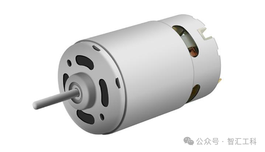
電機(jī)
+關(guān)注
關(guān)注
143文章
9276瀏覽量
149084 -
機(jī)械臂
+關(guān)注
關(guān)注
13文章
553瀏覽量
25327
發(fā)布評(píng)論請(qǐng)先 登錄
極海G32R501工業(yè)六軸機(jī)械臂參考方案釋放工業(yè)4.0產(chǎn)業(yè)價(jià)值
GZCOM-NET:為機(jī)械臂測(cè)試帶來高效無線解決方案!

電機(jī)為什么會(huì)產(chǎn)生軸電流?
大象機(jī)器人攜手進(jìn)迭時(shí)空推出 RISC-V 全棧開源六軸機(jī)械臂產(chǎn)品

大象機(jī)器人攜手進(jìn)迭時(shí)空推出 RISC-V 全棧開源六軸機(jī)械臂產(chǎn)品
電機(jī)聯(lián)軸控制的旋轉(zhuǎn)機(jī)械定轉(zhuǎn)子模態(tài)分析
AGV AMR雙軸機(jī)械臂專用雙伺服電機(jī)驅(qū)動(dòng)控制器帶有STO 高壓隔離CAN RS485 USB通訊 100KH
方案:雙軸伺服電機(jī)驅(qū)動(dòng)控制器AGV、AMR專用雙伺服電機(jī)驅(qū)動(dòng)控制器帶
如何使用PLC控制myCobot 320機(jī)械臂
機(jī)械臂的高效運(yùn)作,連接器起關(guān)鍵作用
在單個(gè)C2000?MCU上使用FCL和SFRA進(jìn)行雙軸電機(jī)控制

帶你了解中空軸步進(jìn)電機(jī)作用
【原創(chuàng)】 drawbot 平面機(jī)械臂scara寫字畫畫機(jī)器人DIY教程貼
OrangePi AIpro應(yīng)用:機(jī)械臂應(yīng)用開發(fā)指南


 工商網(wǎng)監(jiān)
評(píng)論